
2026 Top PVD Coating Equipment Which Is Best?
Choosing the best PVD Coating Equipment in 2026 starts with the part, not the product brochure. A tool coating line, an optical component, and a semiconductor process may need very different chamber designs. Compare substrate size, coating uniformity, batch capacity, and process repeatability before comparing headline prices. Small details matter: fixture spacing, target changes, and how quickly a chamber returns to production.
SEMI’s December 2024 forecast projected global semiconductor manufacturing equipment sales of $125.5 billion in 2025 and $138.1 billion in 2026. Those figures cover the wider equipment market, not PVD systems alone. Still, they show the scale of investment around advanced manufacturing—and why buyers should examine process capability, not just purchase cost. There is no universal winner. That matters.
For a realistic shortlist, review deposition method, available process recipes, vacuum performance, automation, installation needs, and local service support. Ask suppliers for coating results on parts similar to yours, with thickness variation and cycle time documented. A polished demonstration is useful, but production data is better. Even so, one test run rarely reveals long-term maintenance costs or operator learning curves. I would treat those as open questions, not assume the brochure answers them. This guide compares leading equipment options through practical specifications, application fit, and ownership considerations, helping manufacturers identify the system that suits their process rather than simply the most impressive machine.
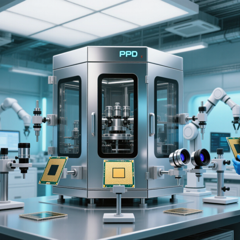
What PVD Coating Equipment Is and How It Works
Physical vapor deposition, or PVD, creates a thin film by moving material from a solid source onto a component inside a vacuum chamber. The equipment typically includes a vacuum pump, a coating source, power controls, gas inlets, and fixtures that hold and rotate parts. The chamber is evacuated, the surface is cleaned, and the source material is vaporized by sputtering, evaporation, or another process. Its atoms travel through the chamber and condense on the component. That is the theory. In practice, surface preparation and temperature control can make or break coating consistency.
The process matters across tools, automotive parts, and electronics, where thin films can improve wear resistance, appearance, or electrical performance. Grand View Research estimated the global PVD market at USD 20.2 billion in 2023 and forecast a 6.2% compound annual growth rate from 2024 to 2030. This market figure covers PVD applications broadly, not equipment sales alone. It signals demand, but it does not identify the right machine for every factory.
Choosing equipment starts with the part. A batch chamber may suit varied, lower-volume components; a continuous system can support repeatable, higher-volume production. Ask for coating-uniformity data on parts similar in size and shape to yours. Check usable chamber dimensions, cycle time, maintenance needs, and energy use. Bigger is not always better. A polished specification sheet can still hide difficult loading or uneven coverage. Run a trial with real parts before committing, and inspect the coating at edges and recesses—not just on a flat test coupon.

Main Types of PVD Coating Systems Available in 2026
PVD coating systems differ in how they create and transport material inside a vacuum chamber. Magnetron sputtering uses a plasma to eject atoms from a target, which then form a thin film on the parts. It offers steady control and can coat complex shapes, though deep recesses may receive less material. Rotation helps. For tools and components needing hard, uniform films, this process is often a practical option.
Cathodic arc evaporation produces a dense coating quickly, making it useful for wear-resistant layers on cutting tools. Tiny droplets can sometimes mark the surface, so finishing requirements matter. Thermal evaporation is simpler and can suit decorative or optical layers, but it may provide weaker coverage on intricate shapes. High-power impulse magnetron sputtering, or HiPIMS, creates highly ionized material for dense films and strong adhesion. It can require more process tuning and energy.
Hybrid systems combine methods to balance film quality, coating speed, and substrate temperature. The right choice depends on part geometry, production volume, material, and the coating’s job—not a headline ranking. Ask for test runs using representative parts, and inspect thickness at edges and inside recesses. A polished sample can hide uneven coverage. There is no perfect system; sometimes the first specification needs revising.
2026 Top PVD Coating Equipment Which Is Best? – Main Types of PVD Coating Systems Available in 2026
| PVD System Type | How It Works | Common Coatings and Applications | Main Advantages | Key Considerations | Best Fit |
|---|---|---|---|---|---|
| Cathodic arc evaporation | An electric arc vaporizes material from a solid cathode. The ionized coating material is directed toward prepared substrates. | Hard nitride and carbon-based coatings for cutting tools, dies, and wear-resistant components. | High ionization and strong coating adhesion; well established for hard, wear-resistant coatings. | Droplets or macroparticles can form on the coating surface. Filtering and process design may reduce them, but can affect deposition rate or system complexity. | Tooling and parts where coating hardness and wear resistance are priorities. |
| DC magnetron sputtering | A plasma bombards a target, ejecting atoms that travel through the vacuum chamber and deposit on substrates. Magnetic fields help sustain the plasma. | Metal and compound films for optical, decorative, electronic, and functional applications; DC is generally used with electrically conductive targets. | Good film uniformity and control; suitable for a broad range of target materials and coating designs. | Reactive processes can require careful control of gas flow and target condition. Electrically insulating targets generally call for RF or another suitable power method rather than DC. | Applications needing controlled, uniform films and flexibility in coating materials. |
| RF magnetron sputtering | Radio-frequency power sustains sputtering and helps prevent charge build-up on electrically insulating targets. | Oxides, nitrides, and other insulating or dielectric films used in optical, electronic, and research applications. | Can deposit materials that are difficult to sputter using a conventional DC supply. | Power supplies and process matching are more involved than for basic DC sputtering; deposition conditions depend on the target and film requirements. | Insulating target materials and applications requiring dielectric or compound films. |
| HiPIMS (High Power Impulse Magnetron Sputtering) | Short, high-power pulses are applied to a magnetron target, producing a highly ionized sputtered flux. | Dense metallic and compound coatings for demanding wear, corrosion, and functional applications. | High ionization can support dense films and improved control of ion bombardment at the substrate. | Requires specialized pulsed-power equipment and process development. Average deposition rate may be lower than conventional magnetron sputtering in some process configurations. | High-performance films where film density and ionized deposition are more important than simple process setup. |
| Electron-beam evaporation | An electron beam heats material in a source crucible or hearth until it evaporates and condenses on substrates. | Optical and electronic films, including metals and selected oxides, depending on source and process design. | Can evaporate many high-melting-point materials and allows separate sources for multilayer coating designs. | The vapor is generally line-of-sight, so fixture design and substrate movement affect coverage. Film density and adhesion may require careful substrate preparation or ion assistance. | Optical and thin-film work requiring precise material layers or evaporation of refractory materials. |
| Ion-beam-assisted deposition (IBAD) | A deposition source forms the film while a separate ion beam simultaneously or sequentially bombards the growing layer. | Optical, protective, and specialized functional films where film structure or adhesion needs additional control. | Provides an independent means of influencing film growth through ion energy and bombardment conditions. | Adds equipment and process complexity. Suitable beam conditions depend on the coating material, substrate, and desired film properties. | Specialized coating processes that need separate control of deposition and ion bombardment. |
| Inline or continuous magnetron sputtering | Substrates move through connected vacuum zones while one or more sputtering sources deposit the film. | Large-area glass, sheet, web, and high-volume production of optical, architectural, and functional coatings. | Supports repeatable, high-throughput production and multilayer processes across large substrate areas. | Requires substantial floor space, vacuum infrastructure, and production planning. System configuration must match substrate dimensions and throughput needs. | Large-area or high-volume manufacturing where continuous processing is practical. |
Selection note: The best PVD system depends on coating material, substrate geometry, required film properties, production volume, and available process support. Deposition temperature, rate, and achievable film quality vary with the specific equipment and process recipe.
Key Factors for Evaluating PVD Equipment
Choosing the best PVD coating equipment starts with the parts you actually make. Record their dimensions, materials, batch sizes, and required coating performance. A chamber that fits large components may waste energy and time on small batches. Fit matters. Check how fixtures hold parts and whether the layout supports consistent coating across edges and recesses. Ask for test results using representative parts, not only polished sample coupons.
Process control deserves close attention. Review vacuum stability, temperature control, gas flow, and monitoring tools. These affect repeatability, especially when substrates vary in shape or heat sensitivity. Ask how operators detect a drift before an entire batch is affected. Also consider pump maintenance, target changes, cleaning time, and access to replacement components. A fast cycle is not always a productive one. Downtime counts. Compare usable output per shift, not just the advertised deposition rate. There is no perfect setup, and I would not pretend otherwise: the right balance depends on your workload. Request a trial run with your own parts, then inspect coating thickness and adhesion at several locations. Test real parts. A careful evaluation may reveal gaps in your assumptions, which is useful before purchase.
2026 PVD Coating Equipment: A Vacuum-Pressure Comparison
The chart shows representative operating-pressure setpoints, not fixed specifications: thermal evaporation commonly operates at much lower pressure than sputtering or cathodic arc deposition. Actual ranges depend on the process and equipment. Pressure is only one selection factor; also evaluate coating requirements, part geometry, throughput, and temperature limits.
Comparing Leading PVD Systems by Performance and Cost
Choosing a PVD system means balancing coating consistency, output, and the cost of keeping the chamber productive. A batch sputtering system can suit mixed part sizes and frequent recipe changes. It requires more operator handling, and each load spends time in pump-down and cooling. Inline systems can process repeat parts steadily, but only when demand supports their footprint and maintenance needs. For hard, decorative coatings, arc-based systems may deposit quickly; however, droplets can affect surface finish. Magnetron sputtering often produces smoother films, though rates and material choices depend on the setup. Small details matter. Check actual samples.
Purchase price is only one line in the budget. Compare power use, target or source replacement, vacuum-pump service, fixture loading, and rejected parts over a typical month. Ask for cycle-time data using your part geometry, not a simple test coupon. Request coating-thickness maps and adhesion results across a full rack. A cheaper chamber may cost more if it limits batch size or needs frequent cleaning. Conversely, high automation can sit idle when orders fluctuate. That sounds neat on paper; real schedules are messier. Run a pilot, calculate cost per accepted part, and allow for training and downtime.
Choosing the Best PVD Coater for Your Application
The best PVD coater is not simply the largest or fastest machine. It is the one that fits your parts, coating goals, and production rhythm. Start with the substrate and geometry: a flat steel tool, a polished component, and a deep cavity place different demands on fixturing and film coverage. Small details matter. Request sample runs with your actual parts, not just demonstration coupons.
Define success before comparing equipment. For cutting tools, wear resistance may be the priority; for decorative parts, color consistency and surface appearance may matter more. Check process options, chamber capacity, usable load space, temperature limits, and part rotation. Ask how coating thickness and adhesion are verified, and whether results are recorded for each batch. A brochure rating is not proof. That is an easy mistake to make.
Consider operators and maintenance, too. Check setup time, target replacement, cleaning intervals, training needs, service access, and energy use. A lower purchase price may conceal higher downtime or consumable costs. Request a realistic cycle time and a written acceptance plan. If possible, run several batches and inspect edge coverage, color variation, and adhesion after handling. No machine is perfect. The right choice is the one that consistently meets your critical requirements while allowing process adjustments as products change.
Article Source:
At Premium PSU, we are specialists in designing and manufacturing power conversion systems for the industrial market. Our product range includes high reliability power supplies from 50W to 72kW.
PREMIUM PSU
C/ Dolors Aleu, 19-21, 2nd Floor
08908 – Hospitalet de Llobregat
Barcelona-SPAIN
t.+34 93 223 26 85