10 Buck Converter Tips for Choosing the Right Model?
Choosing the right buck converter is rarely just a matter of matching input and output voltage. A 12 V rail powering a sensitive sensor behaves differently from a 24 V industrial line driving a motor controller. Current demand, switching frequency, heat, noise, and board space all influence the decision. Small details matter.
This guide presents ten practical tips for evaluating each buck converter model with greater confidence. It considers efficiency at light and heavy loads, peak current limits, voltage ripple, transient response, and protection features. It also explains why datasheet graphs deserve careful attention. A converter showing 95% efficiency at one operating point may perform differently inside a compact, poorly ventilated enclosure. Real conditions can be less generous.
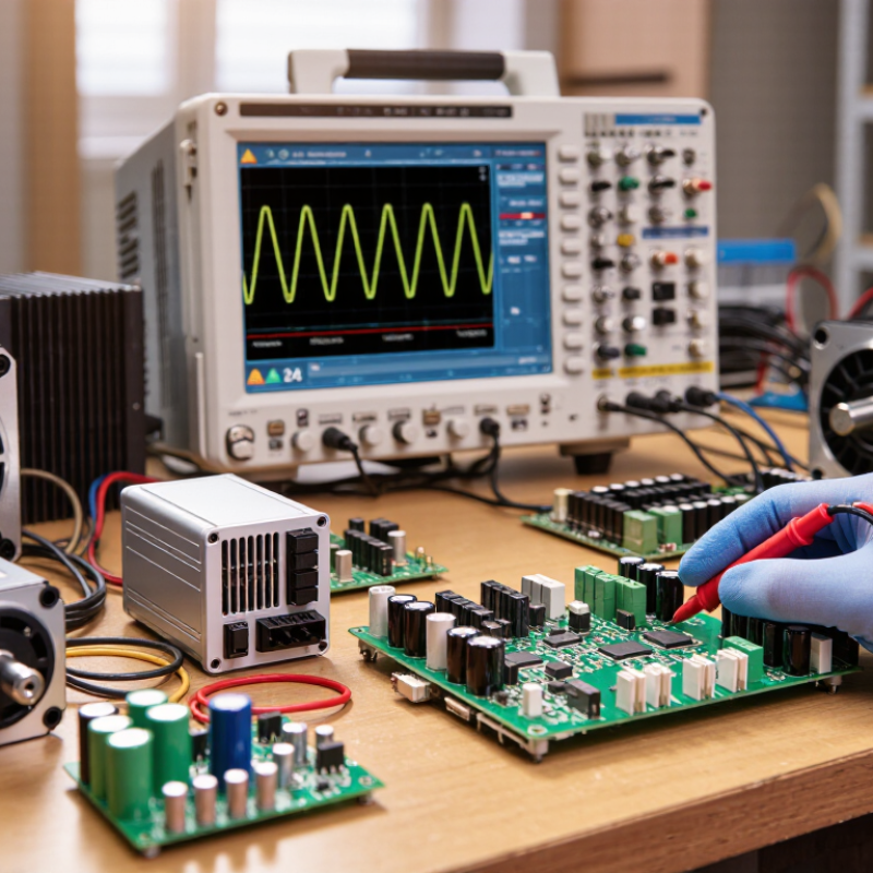
Good engineering combines calculations with verification. Measure the expected load, inspect the recommended layout, and compare thermal behavior under realistic airflow. An oscilloscope can reveal ringing that a multimeter will never show. That matters. Selecting a part only by its lowest price is tempting, but it can create unexpected redesigns later. I have seen apparently suitable components struggle when startup current, cable resistance, or capacitor aging was overlooked. The selection process is not perfect, either. Datasheets may omit important application details, and laboratory results cannot represent every product environment. These limitations deserve honest consideration.
Use the following tips as a structured starting point, not as a substitute for testing. The best buck converter is the model that remains stable, cool, efficient, and predictable in your actual system.
Understanding Buck Converter Basics and Operating Principles
A buck converter reduces a higher DC voltage to a lower one through controlled switching. Its main parts are a switch, inductor, diode or synchronous switch, capacitor, and feedback loop. When the switch turns on, current rises through the inductor. When it turns off, stored magnetic energy continues feeding the load. This repeated action creates a stable output voltage. In continuous conduction, the ideal relationship is Vout ≈ D × Vin, where D represents duty cycle. Real circuits lose energy through resistance, switching transitions, and magnetic-core losses.
The International Energy Agency’s Electricity 2024 report indicates that data-center electricity demand could exceed 1,000 TWh by 2026 in its high-growth case. Efficient voltage conversion is becoming less optional. Recent IEEE power-electronics studies commonly report 90–98% peak efficiency for well-designed buck stages, although thermal conditions can reduce it sharply. Heat still matters. A converter rated for 10 amps may require serious airflow, copper area, and thermal testing. Check ripple current, switching frequency, load transients, and minimum input voltage before choosing a model. I have found that a first efficiency calculation is rarely enough; bench measurements often reveal unexpected noise or heating. Layout quality also affects stability. Keep high-current loops short, place input capacitors close to switching devices, and inspect the waveform with suitable probing. A smaller inductor may save space, but it can increase ripple and acoustic noise. The compromise is easy to underestimate.
Defining Voltage, Current, and Power Requirements
Choosing a buck converter begins with numbers, not package size. Write down input voltage, output voltage, load current, and operating hours. A 24 V rail feeding a 5 V sensor at 0.8 A needs a different design from a 12 V, 2 A motor load. Measure the real load. Peak current can exceed the average during startup, wireless transmission, or relay switching. I have seen otherwise suitable converters reset because the design used only the idle current.
Calculate output power as voltage multiplied by current, then allow practical headroom. For a 5 V, 2 A output, the load requires 10 W, but the converter should not run continuously at its limit. A 20–30 percent margin is a useful starting point, though temperature and airflow may demand more. Check efficiency across the full input range, not only at the typical voltage. Losses become heat. Estimate thermal rise from datasheet curves, enclosure size, and nearby heat sources. One weakness in my own early selections was trusting nominal values too much. Real batteries sag, and supply lines carry noise.
Also verify whether current ratings are continuous or peak values. Confirm startup behavior, minimum input voltage, switching frequency, ripple, and protection limits. A converter that meets the wattage may still fail a sensitive analog circuit. Use an oscilloscope and a resistive load when possible. A quick bench test reveals dips that a spreadsheet misses. Do not skip it. Record measurements at cold start and after the enclosure reaches operating temperature. That evidence makes the final model choice more defensible and easier to review later.
Comparing Efficiency, Switching Frequency, and Thermal Performance
10 Buck Converter Tips for Choosing the Right Model
Comparing Efficiency, Switching Frequency, and Thermal Performance
Choosing a buck converter starts with the load, not the product label. Measure input voltage, output voltage, peak current, and expected load changes. A converter rated for 5 A may overheat near that limit, especially inside a sealed enclosure. Leave practical headroom.
Efficiency affects battery life and heat. During bench testing, record efficiency at light, typical, and peak loads. A device reaching 95% efficiency at full load may perform poorly at 100 mA. Small losses matter in portable equipment. Check the datasheet conditions carefully. They may not match your circuit.
Switching frequency creates a real trade-off. Higher frequency can reduce inductor size and improve transient response, but it often increases switching loss and electromagnetic noise. Lower frequency may improve efficiency, yet it can require larger magnetic components. Thermal performance depends on more than efficiency. Inspect the package, copper area, airflow, and nearby heat sources. Use a thermocouple near the switching node and inductor during extended operation.
Keep testing realistic. Add startup events, cable resistance, and sudden load steps. I once trusted a short thermal test and missed a slow temperature rise after fifteen minutes. That mistake changed my design process. Review the temperature curve, not only the final reading. A cooler converter with slightly lower peak efficiency can be the safer choice. Clearance and layout still matter. Tiny shortcuts become expensive rework.
Evaluating Control Features, Protection, and Component Compatibility
10 Buck Converter Tips for Choosing the Right Model?
A buck converter should match the load, not only the voltage table. The IEA’s Electricity 2024 report projects strong growth in data-centre power demand through 2026. That trend makes efficiency, thermal control, and standby behavior more important. Select a converter with adjustable frequency, soft start, and a documented feedback loop. Current-mode control usually improves transient response. However, poor layout can still create ringing and unstable behavior. Tip: Test the control loop with the real PCB, not only the datasheet circuit.
Protection features need practical evaluation. Check cycle-by-cycle current limiting, short-circuit recovery, input undervoltage lockout, thermal shutdown, and output overvoltage protection. IEC 62368-1 emphasizes energy-related safety, but system-level protection remains the designer’s responsibility. A converter may survive a short circuit while the inductor overheats. That detail is easy to miss. Use an oscilloscope and thermal camera during startup, load steps, and repeated faults.
Component compatibility is equally decisive. Verify the inductor’s saturation current, capacitor ripple rating, ESR range, diode recovery behavior, and MOSFET voltage margin. IPC-2221 guidance supports careful PCB spacing and thermal design, yet real layouts often perform differently from simulations. Tip: Leave at least 20% practical voltage and current margin when conditions allow. My own imperfect rule is to question every “typical” value. It may fit the test board, but not your cable length, enclosure, or production tolerance.
| Tip | Evaluation Area | What to Check | Practical Design Guidance | Why It Matters |
|---|---|---|---|---|
| 1Match the Input-Voltage Range | Electrical operating window | Compare the converter's minimum and maximum input ratings with the nominal source voltage, tolerance, transients, and startup conditions. | Allow margin above the highest expected input. For a nominal 12 V rail, a design may need to tolerate approximately 10.8–13.2 V for a ±10% source variation, plus transient protection. | An insufficient voltage rating can cause overstress, shutdown, or permanent damage during surges. |
| 2Verify Output Voltage and Accuracy | Regulation performance | Review the adjustable-output range, feedback reference tolerance, line regulation, load regulation, and remote-sense options. | Calculate the feedback resistors from the manufacturer's reference-voltage equation. Include resistor tolerance, temperature drift, and PCB leakage in the accuracy budget. | Accurate regulation protects downstream digital, analog, and power-sensitive loads from undervoltage or overvoltage conditions. |
| 3Size for Continuous and Peak Load Current | Current capability | Check the rated output current, peak current limit, short-circuit behavior, and thermal derating at the actual switching frequency and ambient temperature. | Do not select a model only from the nominal load. Account for startup, motor or capacitor charging, processor bursts, and tolerance. Keep normal operation below the thermal current limit. | Peak-current margin reduces current-limit events, output-voltage droop, and unexpected resets. |
| 4Choose the Appropriate Control Mode | Control features and transient response | Compare voltage-mode, current-mode, constant-on-time, pulse-frequency modulation, pulse-skipping, and forced-continuous operation. | Current-mode control can simplify compensation and improve line response. Forced-continuous mode reduces light-load frequency variation but may increase light-load losses. Pulse-skipping or PFM generally improves light-load efficiency. | Control-mode selection affects efficiency, ripple, audible behavior, electromagnetic interference, and response to rapid load changes. |
| 5Evaluate Switching Frequency | Efficiency, size, and noise | Review the fixed or programmable switching frequency, synchronization capability, minimum on-time, and frequency-foldback behavior. | Higher frequency can reduce inductor and capacitor size, but switching losses usually increase. Confirm that the required duty cycle satisfies the controller's minimum on-time and off-time limits. | The switching frequency influences component size, thermal performance, EMI filtering, and the usable input-to-output voltage ratio. |
| 6Select Compatible Inductor and Capacitors | External component compatibility | Check inductance range, saturation current, RMS current, capacitor type, voltage rating, ESR limits, ripple-current rating, and DC-bias derating. | A common starting point is an inductor ripple current of about 20–40% of the maximum output current. Select capacitors with voltage ratings above the maximum output voltage and verify effective capacitance under bias. | Incorrect component selection can cause excessive ripple, instability, overheating, audible noise, or inductor saturation. |
| 7Check Stability and Compensation Requirements | Feedback-loop behavior | Determine whether the model uses internal compensation, external compensation, or a restricted output-capacitance range. | Follow the recommended LC range and capacitor ESR limits. If external compensation is required, calculate the network for the selected inductance, capacitance, crossover frequency, and load range. | A converter may regulate at nominal conditions yet become unstable when the output capacitor, inductor, or load differs from the validated design. |
| 8Review Protection Functions | Reliability and fault handling | Look for input undervoltage lockout, cycle-by-cycle current limiting, short-circuit protection, thermal shutdown, overvoltage protection, and power-good signaling. | Prefer protection thresholds and restart behavior that match the system's fault policy. Check whether the device latches off, hiccups, folds back, or automatically restarts after a fault. | Protection behavior determines whether a fault remains contained or causes repeated stress, overheating, or system-wide interruption. |
| 9Use Soft Start and Enable Features | Startup and sequencing | Check soft-start duration, enable-threshold accuracy, power-good timing, tracking options, pre-bias startup capability, and discharge or output-discharge functions. | Soft start limits inrush current and reduces output overshoot. Confirm that the device can start correctly when the output already has a residual voltage from another supply. | Proper sequencing prevents false resets, excessive input droop, inrush-related shutdown, and conflicts between multiple power rails. |
| 10Validate Thermal and Layout Requirements | Thermal design and PCB implementation | Review package thermal resistance, exposed-pad requirements, copper-area recommendations, switching-node layout, grounding, and current-sense routing. | Keep the high-current input loop short, place the input bypass capacitor close to the power pins, minimize the switching-node copper area, and provide adequate thermal copper. Estimate losses using efficiency data across the full load range. | Good layout and thermal design reduce EMI, voltage overshoot, temperature rise, and sensitivity to parasitic inductance. |
Selecting the Right Buck Converter for the Application
Selecting a buck converter starts with the application, not the catalog headline. Define the input range, regulated output, peak load, and acceptable ripple. A 12 V rail feeding a digital sensor differs greatly from a motor-control supply. Check startup current and load transients, because average current can hide brief overloads. Choose a model with practical voltage and current margin.
Efficiency matters, but heat decides whether the design survives. Estimate losses at the highest input voltage and maximum load. Then inspect the thermal path, copper area, airflow, and enclosure temperature. Thermal margin matters. A converter rated for 5 A may require substantial cooling to deliver that current continuously. Switching frequency also affects inductor size, efficiency, and electromagnetic noise. Higher frequency can save board space, but it may increase switching losses.
Review the control mode and behavior during light loads. Some circuits enter pulse-skipping operation, which can disturb sensitive analog measurements. For noisy environments, examine ripple specifications, layout guidance, and filtering requirements. Keep high-current loops short, place input capacitors close to the switching path, and separate sensitive traces from rapid voltage nodes. Measure it. In one prototype, I focused on efficiency and overlooked connector resistance; the output dipped during startup. That mistake reinforced the need to test the complete assembly, not only the converter board. Verify performance across temperature, input variation, load steps, and fault conditions before approving the model.
Related Posts
-
How to Choose the Right Buck Converter?
-
Best DC Converter Types for Efficient Power Conversion?
-

10 Essential Tips for Understanding and Using Buck Converters Effectively
-
2026 Best Buck Converter Reviews and Buying Guide?
-
Ultimate Tips for Choosing the Right Buck Converter?
-
Why Use a Buck Converter for Efficient Power Management?

At Premium PSU, we are specialists in designing and manufacturing power conversion systems for the industrial market. Our product range includes high reliability power supplies from 50W to 72kW.
PREMIUM PSU
C/ Dolors Aleu, 19-21, 2nd Floor
08908 – Hospitalet de Llobregat
Barcelona-SPAIN
t.+34 93 223 26 85