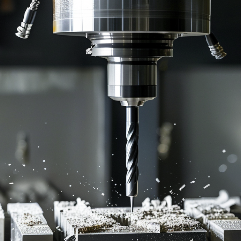
How to Choose Milling Cutters in 2026?
Choosing Milling Cutters in 2026 requires more than matching a tool diameter to a machine spindle. Modern workshops must balance material behavior, cutting speed, coolant delivery, machine rigidity, tool life, and surface-finish targets. A cutter that performs well in aluminum may fail quickly in hardened steel. The same tool can also behave differently on a rigid five-axis machine and an aging vertical mill.
Dr. Tony L. Schmitz, a respected machining researcher and author, has said, “The process is only as good as the information used to control it.” That principle remains practical. Before selecting Milling Cutters, operators should inspect the workpiece material, fixture stability, spindle power, and required tolerance. A 63-millimeter indexable face mill may remove stock quickly, but a smaller solid carbide end mill could produce a cleaner corner. Small details matter.
This guide examines cutter geometry, substrate selection, coatings, flute count, helix angle, and toolpath strategy for 2026 applications. It also considers newer demands, including dry machining, automated tool monitoring, and lower energy consumption. Manufacturer data is useful, yet it should not replace a controlled trial. Real cutting conditions often expose weaknesses that catalog charts hide. That is where judgment develops.
There is no universal best cutter. Sometimes the recommended option still creates vibration. Sometimes a cheaper tool delivers better results. Careful measurement remains essential. Use cutting data as a starting point, then adjust gradually while recording load, noise, chip shape, tool wear, and surface quality.
Understanding Milling Cutter Types and Their Main Applications
Choosing a milling cutter in 2026 starts with the operation, not the catalog. Face mills suit broad, flat surfaces and remove material efficiently. End mills handle slots, pockets, shoulders, and contouring. Ball-nose cutters create smooth three-dimensional profiles, especially in molds and aerospace components. Geometry matters.
A 2024 report from Grand View Research valued the global cutting tools market at more than 23 billion U.S. dollars. It also identified carbide tools as a major growth segment, supported by high-speed machining and harder workpieces. Carbide end mills generally resist wear better than high-speed steel, but they can fail quickly under vibration. I have seen a seemingly perfect cutter chip because the setup was unstable. The machine, fixture, and coolant still matter.
Match the cutter to the material and cutting load. Use a coarse-pitch face mill for heavy stock removal, then switch to a finer-pitch tool for surface quality. For aluminum, sharp flutes and generous chip space help prevent built-up edges. For hardened steel, a short, rigid ball-nose cutter can reduce deflection during finishing. A 2023 report by MarketsandMarkets projected continued expansion in computer numerical control machining, increasing demand for application-specific tooling. That trend is real, but specifications can mislead. Test one controlled cut, inspect chip shape, tool wear, and wall accuracy, then adjust speed, feed, or engagement. No cutter works everywhere.
Matching Cutter Geometry to Material and Machining Requirements
How to Choose Milling Cutters in 2026?
Cutter geometry must match both the workpiece and the machining goal. For aluminum, use polished flutes, a high helix, and generous chip space. These features reduce built-up edge when cutting soft, sticky material. The U.S. Geological Survey reported global primary aluminum production at about 72 million tonnes in 2024, showing why aluminum machining remains significant across manufacturing.
Steel needs a different response. A variable-pitch carbide cutter can reduce vibration, while a moderate helix supports stable shoulder milling. Hard stainless steel often benefits from fewer flutes and stronger cutting edges. According to World Steel Association data, global crude steel output reached approximately 1.88 billion tonnes in 2024. That volume does not guarantee easy cutting. Heat, work hardening, and interrupted cuts still challenge tool life.
Match geometry to the operation, not only the material. Choose more flutes for high-feed finishing when chip evacuation remains safe. Use fewer flutes for deep slots, especially when coolant access is limited. ISO 8688-2 provides standardized methods for evaluating milling tool life, but shop conditions can distort laboratory expectations. I still check tool wear after the first trial pass. The first setting is rarely perfect. A cutter that survives one alloy may fail quickly on another batch. Record spindle load, cutting sound, burr formation, and edge wear before changing speed or feed. Small observations often reveal a geometry mismatch earlier than tool failure.
How to Choose Milling Cutters in 2026? — Matching Cutter Geometry to Material and Machining Requirements
| Workpiece Material | Typical Machinability | Recommended Cutter Geometry | Flute Count | Helix Angle | Rake and Relief Guidance | Tool Material and Edge Preparation | Starting Cutting Guidance | Main Machining Concern |
|---|---|---|---|---|---|---|---|---|
| Aluminum Alloys | High to moderate Good thermal conductivity, but some grades are prone to built-up edge. | Sharp cutting edges, polished flutes, and large chip gullets. Variable-pitch geometry is useful for reducing chatter. | 2–3 flutes for slotting and high chip evacuation; 3–5 flutes for general profiling. | 35°–50° | Positive rake, typically about 10°–20°; moderate to high relief to reduce rubbing. | Fine-grain carbide with a sharp, honed or minimally honed edge. Polished, low-friction flute surfaces are preferred. | Cutting speed: 150–600 m/min Use high feed per tooth when machine rigidity and chip evacuation permit. | Prevent built-up edge with adequate air blast, mist, or suitable coolant; avoid dwelling. |
| Low-Carbon and Mild Steel | Moderate to good Generally stable, but long chips may form. | General-purpose variable-helix end mill with a balanced core and chip space. Unequal flute spacing helps suppress vibration. | 4–5 flutes for profiling; fewer flutes for deep slotting. | 30°–45° | Moderately positive rake; standard relief is usually sufficient for stable cuts. | Carbide with a wear-resistant multilayer coating suitable for ferrous materials. A small edge hone improves edge strength. | Cutting speed: 80–220 m/min Adjust feed according to cutter diameter, radial engagement, and machine power. | Control long chips and avoid excessive radial engagement that can overload the tool. |
| Alloy and Pre-Hardened Steel | Moderate to difficult Higher strength and abrasive alloying elements increase cutting loads. | Variable-pitch geometry, strong core, and unequal helix are suitable for roughing and finishing. | 4–5 flutes for general work; 5–7 flutes for finishing when chip space remains adequate. | 35°–45° | Moderately positive rake with a stronger edge than an aluminum cutter; use a controlled edge hone. | Fine-grain carbide with a heat- and wear-resistant coating. Choose a tougher grade for interrupted cuts. | Cutting speed: 60–180 m/min Prefer constant tool engagement and adaptive or trochoidal paths for heavy roughing. | Excessive heat, vibration, and interrupted entry can cause edge chipping or premature flank wear. |
| Stainless Steel | Moderate to difficult Work-hardening and low thermal conductivity are common challenges. | Variable-helix cutter with a strong edge, efficient chip evacuation, and geometry designed to maintain positive cutting action. | 4–5 flutes for profiling; use fewer flutes where chip evacuation is restricted. | 35°–45° | Positive rake with a stronger edge hone; avoid a blunt edge that increases rubbing and heat. | Tough carbide with a coating designed for heat and adhesion resistance. Sharp but sufficiently supported edges are preferred. | Cutting speed: 50–140 m/min Maintain a positive feed; do not allow the tool to rub or remain stationary in the cut. | Avoid work-hardening by using adequate chip load, stable toolholding, and consistent engagement. |
| Gray Cast Iron | Moderate Graphite improves chip breaking, but abrasive particles accelerate wear. | Rigid geometry with strong cutting edges and sufficient flute space for dry or air-assisted machining. | 4–6 flutes for profiling; select flute count according to dust and chip evacuation needs. | 30°–45° | Neutral to moderately positive rake; a robust edge hone is useful for resisting micro-chipping. | Wear-resistant carbide coating. Diamond tooling may be considered for suitable non-ferrous cast materials, but not for ferrous cast iron. | Cutting speed: 80–250 m/min Use air blast or dry cutting where appropriate; avoid contaminating coolant systems with abrasive fines. | Abrasive dust causes rapid wear; protect guideways and use effective chip and dust extraction. |
| Titanium Alloys | Difficult Low thermal conductivity and high strength create concentrated heat at the cutting edge. | Variable-helix cutter with a strong core, efficient chip evacuation, and geometry that maintains a continuous cutting action. | 4–6 flutes for profiling; use fewer flutes when deep pockets limit chip evacuation. | 35°–45° | Moderately positive rake with a strong edge hone; avoid excessive edge sharpness in interrupted cuts. | Tough carbide with a heat-resistant coating. Use a stable toolholder and minimize tool runout. | Cutting speed: 25–80 m/min Use generous coolant delivery and a constant-engagement toolpath where possible. | Do not dwell or rub. Heat accumulation can rapidly damage the edge and work-harden the surface. |
| Nickel-Based Superalloys | Very difficult High strength at temperature, work-hardening tendency, and poor heat transfer. | Strong-core variable-pitch cutter with a reduced radial engagement strategy and highly controlled chip thickness. | 4–6 flutes, selected to preserve adequate chip space for the programmed engagement. | 35°–45° | Positive but conservative rake; strong edge preparation is essential to reduce chipping. | Tough, fine-grain carbide with a heat-resistant coating. Replace the cutter before severe wear changes the cutting geometry. | Cutting speed: 15–50 m/min Use high-pressure coolant when compatible with the machine and workholding setup. | Maintain continuous cutting and avoid excessive tool engagement, dwell, and repeated recutting of chips. |
| Hardened Tool Steel, 50–60 HRC | Very difficult High hardness and interrupted cutting can cause edge fracture. | Small-diameter, rigid cutter with variable pitch, strong core, and geometry optimized for light radial and axial engagement. | 4–6 flutes for finishing; use the highest flute count that still provides reliable chip evacuation. | 30°–45° | Neutral to slightly positive rake with a robust micro-honed edge; avoid fragile sharp edges. | Fine-grain carbide with a hard, heat-resistant coating. Specialized cutting materials may be selected for stable finishing operations. | Cutting speed: 40–120 m/min Use light radial engagement, high spindle speed where appropriate, and stable finishing passes. | Rigidity, runout, and thermal stability are critical; excessive engagement can cause immediate edge failure. |
| Engineering Plastics | Material-dependent Some plastics melt, smear, or deform instead of producing clean chips. | Very sharp polished edges, large chip gullets, and flute geometry that limits heat generation and chip recutting. | 1–2 flutes for soft plastics and deep pockets; 2–3 flutes for harder engineering plastics. | 30°–45° | High positive rake with generous relief to reduce rubbing and melting. | Sharp carbide is commonly used. Polished flute surfaces and low runout are more important than a heavy edge hone. | Cutting speed: 100–500 m/min Use air blast and sufficiently high feed to create chips rather than heat. | Prevent melting through sharp tools, effective chip evacuation, adequate feed, and controlled heat input. |

Selecting Cutter Diameter, Tooth Count, and Cutting Edge Design
How to Choose Milling Cutters in 2026?
Selecting Cutter Diameter, Tooth Count, and Cutting Edge Design
Choosing a milling cutter starts with the workpiece, machine rigidity, and available spindle power. Cutter diameter affects stiffness, cutting force, and the toolpath around corners. A larger cutter can remove material efficiently and reduce deflection. However, it may require more torque and leave limited access in narrow areas. Measure the pocket and fixture carefully. Clearance is often overlooked.
Tooth count controls chip space and possible feed rates. Fewer teeth create larger gullets, helping remove chips from aluminum or deep slots. More teeth can improve finishing in steel when the machine maintains stable feed and speed. Do not select teeth by appearance alone. Check the required chip load and actual spindle capacity. I usually begin conservatively, then inspect chip shape, sound, and surface marks.
Cutting edge design must match the operation. A sharp edge suits softer materials, while a honed edge can resist small impacts in harder alloys. Chamfered edges offer useful strength during interrupted cuts. Ball-nose profiles work well on curved surfaces but may cut inefficiently near the center. Variable helix designs can reduce chatter, although they are not a cure for weak workholding. My first selection is not always correct. A cutter that performs well in one fixture may vibrate badly in another. Record the result, adjust one variable, and test again.
Choosing Coatings, Tool Materials, and Performance Features
Choosing Milling Cutters in 2026: Coatings, Tool Materials, and Performance Features
The workpiece material should guide your cutter choice, not habit. For hardened steels, fine-grain carbide offers stiffness and edge strength. High-speed steel remains useful for slower machines and interrupted cuts. It is less productive, but sometimes more forgiving. Aluminum usually benefits from polished carbide flutes and a sharp, high-helix geometry. Avoid excessive edge preparation, which can rub instead of cut.
Coatings change friction, heat resistance, and tool life. Aluminum chromium nitride suits many dry or high-temperature steel operations. Titanium aluminum nitride can perform well during high-speed cutting, especially when heat reaches the cutting edge. For aluminum, an uncoated, polished surface may prevent built-up edge better than a rough coating. Test this carefully. Coating selection is not universal.
Performance features deserve close inspection. Variable helix flutes can reduce vibration on thin walls and long toolpaths. Unequal flute spacing helps when the machine sounds harsh. Internal coolant improves chip evacuation in deep pockets, but it cannot fix poor programming. A 12-millimeter cutter may seem rigid, yet excessive stickout can still cause chatter. Keep it short.
In my machining experience, catalog ratings often assume ideal setup conditions. Real fixtures flex. Operators adjust feeds. Tool life can fall sharply after one small change. Record spindle speed, feed per tooth, radial engagement, and edge wear. Then compare results on the same material batch. Some choices will fail. That failure is useful evidence, if you document it.
Checking Machine Compatibility, Cutting Parameters, and Tool Life
How to Choose Milling Cutters in 2026?
Machine compatibility comes before cutter geometry.
Check spindle taper, maximum speed, power, coolant delivery, and controller limits. A 40 mm cutter may fit physically but overload a small spindle. The 2024 U.S. Cutting Tool Consumption Report shows continuing demand for high-performance tooling, yet consumption data cannot replace a machine-side check.
Measure runout with a gauge.
Keep it below 0.01 mm where possible. Small errors become visible as uneven teeth marks and premature edge failure.
Cutting parameters should match the cutter, workpiece, and setup.
Use the manufacturer’s recommended chip load as a starting point, then adjust after observing sound, vibration, and chip shape. Taylor’s tool-life equation shows why speed deserves caution.
ISO 8688-2 provides a recognized framework for milling tool-life testing. Record cutting speed, feed per tooth, axial depth, radial engagement, and coolant condition.
Guessing is expensive.
Tool life is not only minutes on the spindle.
It includes edge quality, dimensional drift, and the risk of sudden failure. A 2023 CIRP review of machining research emphasizes process monitoring and data-based maintenance for more reliable production.
Still, sensors can mislead. I have seen clean dashboards hide a loose holder.
Inspect the first and last component from every trial batch. Replace the cutter when surface finish or size leaves tolerance, not only when the edge visibly breaks.
Article Source:
At Premium PSU, we are specialists in designing and manufacturing power conversion systems for the industrial market. Our product range includes high reliability power supplies from 50W to 72kW.
PREMIUM PSU
C/ Dolors Aleu, 19-21, 2nd Floor
08908 – Hospitalet de Llobregat
Barcelona-SPAIN
t.+34 93 223 26 85