
How to Choose the Right Quick Coupler in 2026?
Choosing the right Quick Coupler in 2026 is no longer a simple attachment decision. It affects productivity, operator safety, equipment life, and daily operating costs.
A coupler may look compact on a machine. Its impact is much larger. A poor match can create attachment movement, hydraulic stress, uneven loading, and avoidable downtime. The correct choice begins with the excavator’s operating weight, hydraulic configuration, pin dimensions, attachment range, and working environment.
“Compatibility is only the beginning; a coupler must also support safe, repeatable operation,” says Mark Wall, a construction equipment product specialist. This principle deserves attention. Many buyers compare purchase prices first. That can be a costly habit.
In real work, a coupler faces mud, vibration, frozen pins, abrasive dust, and rushed attachment changes. A model that performs well in a clean demonstration may struggle on a demolition site. Manual, hydraulic, and fully automatic systems also involve different inspection routines and operator responsibilities.
Look closely at locking indicators, safety mechanisms, service access, and manufacturer support. Check whether the Quick Coupler meets the excavator’s rated capacity without reducing useful breakout force. Confirm that existing buckets and tools fit correctly.
The best decision is rarely the cheapest one. It is the one that fits the machine, attachments, operators, and working conditions.
There is room for doubt.
Specifications can be incomplete. Field habits can be overlooked. Even experienced teams may underestimate maintenance requirements. This guide examines those details carefully, helping buyers make a more informed Quick Coupler decision for 2026.
What Is a Quick Coupler and How Does It Work?
How to Choose the Right Quick Coupler in 2026?
What Is a Quick Coupler and How Does It Work?
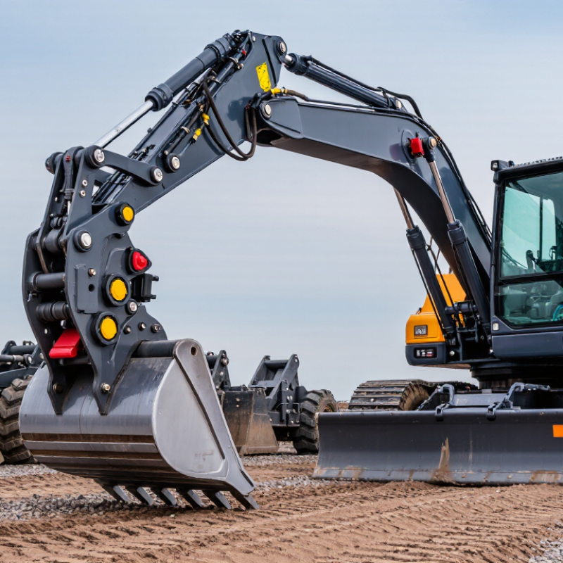
A quick coupler is an attachment device fitted between an excavator arm and a work tool. It allows operators to change buckets, breakers, grapples, or similar attachments without removing the main mounting pins manually. In practical use, this saves time beside the machine and reduces repeated lifting. Small details matter. A coupler must match the attachment pin diameter, spacing, machine weight, and hydraulic capacity.
Most models use a mechanical, hydraulic, or hybrid locking system. The coupler first captures one attachment pin. Its locking hook then engages the second pin and holds the tool against the mounting frame. Hydraulic versions use pressure to move the locking mechanism from the cab. Mechanical designs may require a manual lever or secondary safety lock. Either way, the operator should confirm full engagement before applying force. A visible indicator helps, but it should not replace a physical inspection.
Real job sites are less tidy than product sheets suggest. Mud can hide a locking gap, and worn pins can create unexpected movement. I have learned that quick changes are not always the best choice if inspection becomes rushed. In 2026, buyers should examine lock feedback, service access, replacement parts, and compatibility data. Sensor alerts may improve awareness, but sensors can fail or lose calibration. Choose a coupler with clear operating instructions, documented load limits, and a locking system that workers can verify under ordinary site conditions.

Which Quick Coupler Specifications Match Your Equipment?
Choosing a quick coupler starts with your equipment, not the coupler catalog. Check the excavator’s operating weight, hydraulic pressure, oil flow, and attachment pin diameter. These figures must match closely. A coupler built for higher flow may overheat a smaller hydraulic circuit. That mistake can appear slowly, then become expensive. Measure the pin spacing and ear width with calipers, not by visual estimation. Also check the boom geometry. Limited clearance may prevent full engagement.
The attachment’s weight matters as much as the machine’s capacity. A heavy coupler reduces available lifting power and changes the machine’s balance. Confirm the coupler’s rated load, pin size, working pressure, and connection method. Hydraulic models need compatible hoses, valve control, and adequate flow. Manual models need accessible locking points and clear inspection areas. Safety locking systems should hold the attachment even if pressure drops. Test the fit with the machine stopped and the attachment resting on firm ground. Field conditions are rarely perfect.
Tips: Record every measurement before ordering. Compare the coupler with your heaviest attachment, not your smallest one. Inspect pins for wear and measure oval holes carefully. Ask a qualified technician to verify hydraulic compatibility. I have seen operators trust an old specification sheet, then discover a small dimensional error during installation. Rechecking takes minutes. Rework takes much longer. Leave enough clearance for dirt, paint buildup, and normal movement. A perfect paper match can still perform poorly when maintenance access is ignored.
How to Choose the Right Quick Coupler in 2026?
Quick coupler specifications should match the excavator's operating weight, attachment pin diameter, hydraulic pressure, and coupler weight. The chart below provides typical pin-diameter references for common excavator weight classes. Always verify the exact pin spacing, pin diameter, hydraulic flow, and attachment weight with the equipment manufacturer.
Reference ranges are based on commonly used excavator and attachment configurations. A coupler must be compatible with both the excavator dipper arm and the attachment; pin diameter alone is not sufficient for final selection.
How to Compare Coupler Types, Materials, and Connection Standards
How to Choose the Right Quick Coupler in 2026?
Choosing a quick coupler starts with the connection, not the catalog photo. In field maintenance, I compare flow rate, working pressure, impulse cycles, and contamination risk. Flat-face couplers reduce fluid loss and dirt entry. Poppet couplers often provide strong flow performance. Screw-to-connect designs suit high-pressure circuits but require more time during service. Dry-break couplers add protection where leakage is unacceptable.
Material selection should match the environment. Carbon steel is practical for general hydraulic equipment. Stainless steel performs better near moisture, salt, or aggressive cleaning chemicals. Brass can suit lower-pressure applications, though it is not always the strongest choice. Seal material also matters. Temperature, oil type, and ultraviolet exposure can change seal life. Small details matter.
Connection standards prevent costly mistakes. ISO 16028 commonly supports flat-face hydraulic couplers, while ISO 7241 covers broader hydraulic coupler dimensions and performance requirements. Thread compatibility still needs checking. NPT, BSPP, BSPT, metric, and ORFS threads are not automatically interchangeable. According to a 2024 MarketsandMarkets study, the global hydraulic equipment market is projected to grow at roughly 4% annually through 2029, increasing pressure for reliable component selection. Grand View Research also identifies construction and industrial equipment as major demand areas. Yet market reports use different definitions. I would not treat one forecast as absolute. Confirm the actual mating profile, pressure rating, and test records before ordering. A perfect coupler does not exist. The right one fits the system.
How to Choose the Right Quick Coupler in 2026? — How to Compare Coupler Types, Materials, and Connection Standards
| Coupler Type | Connection Method | Typical Applications | Main Advantages | Main Limitations | Typical Material Options | Common Seal Materials | Relevant Standards | Selection Priorities |
|---|---|---|---|---|---|---|---|---|
| Flat-Face Coupler | Push-to-connect or sleeve-operated connection with flat mating faces | Construction equipment, mobile hydraulics, hydraulic tools, loader attachments, and applications requiring clean disconnection | Low fluid spillage Low air inclusion Easy cleaning Good external contamination control | Usually costs more than basic poppet couplers; dirt or pressure trapped at the interface can make connection difficult; some designs should not be connected under pressure | Carbon steel with zinc or trivalent passivation; stainless steel for corrosive environments | Nitrile rubber for general petroleum-based hydraulic fluids; fluorocarbon rubber for higher temperature or chemical resistance; EPDM for compatible water-glycol or phosphate-ester applications | ISO 16028 | Clean connection, low leakage, contamination control, hydraulic tool compatibility, and required flow capacity |
| Poppet-Type Coupler | Ball or poppet valves open when the two halves are mechanically connected | General industrial hydraulics, agricultural machinery, maintenance lines, and standard auxiliary circuits | Widely available Simple design Good general-purpose performance Broad size range | More fluid loss and air entry than flat-face designs; flow restriction and pressure drop depend strongly on valve geometry and size; exposed valve surfaces can attract contamination | Carbon steel, stainless steel, and sometimes brass for lower-pressure or non-corrosive service | Nitrile rubber is common; fluorocarbon rubber is used when temperature and chemical resistance are required | ISO 7241; ISO 5675 for applicable agricultural quick-action couplings | Existing interface standard, operating pressure, flow rate, allowable pressure drop, and interchangeability requirements |
| Screw-to-Connect Coupler | Threaded sleeve or nut mechanically draws the two halves together | High-pressure hydraulics, hydraulic cylinders, jacking systems, heavy-duty machinery, and circuits exposed to vibration | Strong mechanical connection Good resistance to vibration Suitable for demanding pressure service | Slower to connect; threads must be kept clean; connection may require manual torque; generally unsuitable when rapid attachment changes are essential | Hardened or high-strength carbon steel; stainless steel where corrosion resistance is necessary | Nitrile rubber for standard hydraulic oil; fluorocarbon rubber for elevated temperature and aggressive fluid conditions | ISO 14541 | Pressure rating, vibration resistance, connection frequency, available installation space, and required tightening method |
| Screw-Together Flush-Face Coupler | Threaded connection with flush or near-flush valve faces | High-pressure hydraulic tools, rescue equipment, lifting systems, and applications where leakage and contamination must be minimized | Low leakage High pressure capability Good vibration resistance Clean valve interface | Slower than sleeve-lock designs; connection torque and alignment are important; pressure trapped in either side can prevent connection | High-strength carbon steel with protective coating; stainless steel for corrosive environments | Fluorocarbon rubber is often selected for higher temperature or chemical resistance; seal choice must match the hydraulic fluid | Applicable ISO 14541 or manufacturer-specific interface requirements; verify the exact profile before interchange | Pressure class, trapped-pressure behavior, leakage limits, vibration, and compatibility with the existing tool circuit |
| Breakaway Coupler | Designed to separate when excessive pull or side load occurs, often with automatic shut-off valves | Tractors, implements, mobile equipment, hose protection systems, and circuits exposed to accidental hose pull-out | Protects hoses and ports Reduces accidental damage Can limit fluid loss after separation | Requires correct reset procedure; accidental separation can interrupt operation; pressure drop and breakaway force vary by design | Plated carbon steel; stainless steel for harsh or corrosive environments | Nitrile rubber for common hydraulic oils; other elastomers may be required for water-based or fire-resistant fluids | ISO 5675 may apply to relevant agricultural interfaces; confirm the complete breakaway assembly specification | Breakaway force, reconnection method, hose routing, flow rating, shut-off performance, and compatibility with the host machine |
| Multi-Coupling System | Several hydraulic lines connect simultaneously through a common plate or guided assembly | Quick-change attachments, manufacturing fixtures, mobile machinery, and systems with multiple hydraulic functions | Fast multi-line connection Prevents line mix-up Organized hose routing | Higher initial cost and weight; alignment is critical; maintenance is more involved; one damaged interface can affect the complete assembly | Steel or stainless steel couplers mounted in a steel or engineered structural frame | Seal material is selected separately for each circuit’s fluid, temperature, and pressure conditions | Individual coupler interfaces may follow ISO 16028, ISO 7241, or another specified profile; the complete plate is often application-specific | Number of circuits, simultaneous flow requirements, alignment tolerance, electrical integration, and service access |
| Decision Factor | Common Options | Practical Selection Guidance | Important Verification Data |
|---|---|---|---|
| Body Material | Plated carbon steel, stainless steel, brass, and engineered polymers for selected low-load components | Use plated carbon steel for most general hydraulic service; use stainless steel when salt, moisture, washdown, or corrosive chemicals are present; use brass only when its pressure, fluid, and mechanical limits are suitable | Corrosion exposure, pressure, temperature, impact, weight, and maintenance environment |
| Valve Material | Hardened steel, stainless steel, or corrosion-resistant alloy components | Select valve materials according to wear, contamination, fluid chemistry, and the required cycle life | Valve wear, internal leakage limit, flow path, cycle count, and fluid compatibility |
| Seal Material | Nitrile rubber, fluorocarbon rubber, EPDM, polyurethane, and polytetrafluoroethylene-based sealing elements | Nitrile rubber is widely used with petroleum-based hydraulic fluids; fluorocarbon rubber supports higher temperature and broader chemical resistance; EPDM is used only with fluids known to be compatible with it | Hydraulic fluid type, continuous and peak temperature, pressure, abrasion, and exposure time |
| Nominal Size | Common hydraulic nominal bore categories include DN 6, DN 10, DN 12.5, DN 19, and larger sizes | Choose the smallest size that meets the required flow without excessive pressure drop; nominal size does not by itself define the actual internal passage | Required flow rate, allowable pressure drop, hose inside diameter, port size, and coupler flow coefficient |
| Pressure Rating | Working pressure, peak pressure, impulse pressure, and proof or burst pressure | Never select a coupler from nominal size alone; the complete assembly must meet the highest expected working and transient pressure with an appropriate safety margin | Maximum continuous pressure, peak pressure, pressure spikes, temperature derating, and hose assembly rating |
| Connection Standard | ISO 16028, ISO 7241, ISO 14541, ISO 5675, or a documented application-specific profile | Match the complete interface profile, not just thread diameter or nominal size; couplers from different standards should not be assumed interchangeable | Standard number, series or profile, size, valve type, thread form, gender, and dimensional drawing |
| Connection Under Pressure | Connectable under residual pressure, connectable only at low residual pressure, or not connectable under pressure | Choose a pressure-relieving or designed-under-pressure model only when the manufacturer’s specification explicitly permits it | Residual pressure on each side, trapped-volume conditions, connection force, and safe depressurization procedure |
| Environmental Protection | Dust caps, protective plugs, wipers, corrosion-resistant coatings, and sealed storage arrangements | Use protective caps whenever the coupler is disconnected; contamination control is especially important for flat-face and precision hydraulic systems | Dust, water, mud, salt spray, cleaning chemicals, storage duration, and operating temperature |
How to Evaluate Pressure, Flow, Safety, and Operating Conditions
How to Choose the Right Quick Coupler in 2026?
Pressure and flow should be evaluated together. A coupler rated for 300 bar may still restrict a high-flow hydraulic circuit. Check the system’s maximum working pressure, pressure spikes, and continuous operating temperature. ISO 4413 recommends controlling hydraulic risks through suitable component selection, installation, and maintenance. For pneumatic systems, ISO 4414 provides similar safety guidance. Do not rely only on catalog ratings. Real installations experience vibration, contamination, and repeated connection cycles.
Flow loss matters at the tool. Measure pressure before and after the coupler under working load, not during idle testing. The U.S. Department of Energy reports that compressed-air leaks can waste 20% to 30% of compressor output. A leaking or poorly sealed coupling increases that waste. Small losses become expensive. Coupler materials must also match the fluid, moisture level, and ambient temperature. A clean workshop differs greatly from a dusty construction site.
Tips: Select a coupler with a safety margin, but avoid oversized bodies that add cost and weight. Confirm locking sleeves, residual-pressure release, and accidental-disconnection protection. Mark connection points clearly. Inspect seals regularly. One practical weakness remains: many selection decisions use peak pressure but ignore actual flow demand. That shortcut needs reconsideration. A pressure gauge, flow test, and operating log provide better evidence than assumption.
How to Select, Install, and Maintain the Right Quick Coupler in 2026
Choosing the right quick coupler starts with the machine, not the attachment. Check the excavator’s operating weight, hydraulic pressure, pin diameter, attachment width, and rated lifting capacity. Match these figures with the coupler’s technical data. A hydraulic model can improve speed, but it needs clean oil and suitable hose protection. A manual model may suit simpler work. Confirm the locking system and visible safety indicator before purchase. Small mismatches create expensive wear.
Installation requires a controlled work area and careful preparation. Park on stable ground, lower the attachment, release hydraulic pressure, and clean every contact surface. Inspect pins, bushes, locking hooks, and hoses before connection. After fitting, test the coupler without a load. Then lift the attachment slightly and check the lock visually and physically. Never trust a dashboard signal alone. A checklist helps, but rushed checks still fail.
Daily maintenance should include checking cracks, deformation, loose fasteners, hydraulic leaks, and unusual movement. Remove packed soil around the locking mechanism before lubrication. Follow the service manual for grease type, inspection intervals, and bolt torque. Record wear measurements and repairs, especially on machines used in demolition or abrasive ground. Field inspections often find that operators notice leaks late. That is worth reflecting on. Replace damaged safety parts immediately, and have qualified personnel verify repairs before returning the machine to work.
Article Source:
At Premium PSU, we are specialists in designing and manufacturing power conversion systems for the industrial market. Our product range includes high reliability power supplies from 50W to 72kW.
PREMIUM PSU
C/ Dolors Aleu, 19-21, 2nd Floor
08908 – Hospitalet de Llobregat
Barcelona-SPAIN
t.+34 93 223 26 85